I was recently given a Piccolino and development board. I had little idea of how to set it up, or how to get started. Now that I have worked some of these things out I thought I would share a guide, and hopefully make life easier for others.
Background information
Piccolino was developed via a Kickstarter project that received $69,216(USD) funding in May 2015. The Piccolino is a compact Arduino with integrated OLED, WIFI, SD Card support and 32K of SRAM. The Kickstarter page gives a lot more information that does not seem to be on the Piccolino website.
Hardware
To get started with development for the Piccolino you will need to connect an FTDI programmer. These are available via electronic stores or on eBay. The FTDI programmer can be connected directly to the Piccolino or via a carrier board. These options will be explained in a moment.
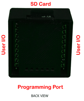
First let’s take a look at the back of the Piccolino. Here you will find two sets of User I/O ports, and the programming port. On the side of the Piccolino the SD card slot can be seen. The SD card slot is spring loaded with a click in/out mechanism.
Note: the alignment of the SD card in the image, the writing on the SD card faces down.
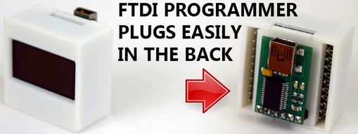
If you do not have a carrier board the FTDI programmer can be connected directly to the Piccolino, plugging its pins into the programming port as in the image below. Bear in mind however, this will not give enough power for the WIFI adapter to run.
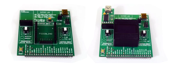
If you also have a carrier board, then the FTDI programmer can be plugged into this. Below shows the carrier board alone and also with the Piccolino and FTDI attached. The FTDI is the small circuit connected to the black port on the left of the Piccolino. On the right of the carrier board is another USB port that can be used to provide power for the WIFI.
When plugging the Piccolino into the carrier board with the case covering it I found it was quite tight between the Piccolino and the connector for the FTDI board. This made removing the Picclino difficult also.
When connecting the FTDI programmer take care as there is little support. I would suggest using a disconnected USB cable so its not powered, plug that into the FTDI programmer, then connect the FTDI programmer to the carrier board before powering the USB cable.
Taking the Piccolino out of its case
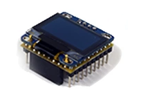
The Piccolino can be removed from its 3D printed case by removing the bottom portion via the finger recess. The case is in two parts, the flat bottom, and the shell that covers the screen. By removing the Piccolino from the case, its clear how the capacitive touch areas on the front work.
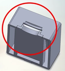
You can see some kind of metal contact on the inside of the case, as well as the pins on the Piccolino that would make contact here. You will note at this stage that the touch sensitive areas are on the left and right below the screen.
Software setup
Let’s get the software set up so that we can run some examples and then finally get into developing our own ideas!
- Get the Arduino IDE
- Get the Piccolino libraries
- Unzip the Piccolino libraries to the Arduino libraries directory. User libraries are located at
C:\Users\<user>\Documents\Arduino\librarieson Windows, and at/Users/<user>/Documents/Arduino/librarieson OSX. The contents of the zip should be in the libraries folder,...Arduino\libraries\Piccolino_IOas an example. The Piccolino libraries include examples and libraries for development. - Open the Arduino IDE and set the port and board type
- Select
Tools -> Board -> select 'Arduino Pro or Pro Mini'. This should also set the processor to ATmega328. If not do this manually. - Select
Tools -> Port -> select the port. If you only see COM1 you may need to install some FTDI drivers.
- Select
Load an example
Now we will load up an example, this will show you the process of checking that the code is correct, and upload it onto the Piccolino. I will also show you how to see the serial output from the Piccolino.
- In the Arduino IDE click
File -> Examples -> Piccolino_OLED -> hello_world. - We can then check to make sure there are no errors in the program. Click the “Verify” button, which looks like a tick. If there are any errors they will show in the console at the bottom of the window.
- To upload it to the Piccolino, click the “Upload” button, which looks like an arrow pointing to the right. You will see the status change at the bottom of the Arduino IDE window.
- The demo should now start to run on the Piccolino. It will show some text in different sizes, draw some lines, and move
Hello world”` around.
Get serial output
Some of the programs have text output on the serial connection, this might be handy for print debugging or communicating with a process running on a computer.
- Using the Arduino IDE, upload an example that uses serial communication. EG:
Piccolino_Ram -> piccolino_ram_test. - When this is running there should be no output on the Piccolino screen, and if there was another program running before the upload the screen may continue to display what was on screen when the upload happened.
- Go to
Tools -> serial monitoror click the magnifying glass icon on the right side of the Arduino IDE toolbar. You should seeTesting 90123456print out repeatedly.
Reinstate the initial program
The initial demo (at least on my piccolino) was a cat moving back and forth. If you touched the capacitive buttons text was shown. This can be retrieved from GitHub and uploaded to the Piccolino.
So go get started!
This should be enough information to get you started on development. So get to it! To see how to draw an image on the Piccolino see my next post.